Week 07: Computer-controlled Machining
Why CNC?
Computer Controlled Cutting has fundamentally changed industrial production. There are many advantages compared to previous production methods:
- Production is less prone to errors
- Accuracy is much better than what you can achieve by hand
- Flexibility: With one machine, you can produce many different things, thus enabling a wide range of manufacturing capabilities
- The more axes a machine has, the more complex the things it can produce
- With more axes, we can produce more complex objects
This week, we will be working with a two-axis machine. There are also various machines that can be handheld, such as the Handibot.
There are many materials that could be cut:
- Alucobond
- Acrylic
- Polycarbonate
- Extruded Polystryrene XPS
- Polypropylene
- Nylon
- POM
- Wax
- MDF
- Hard wood
- Cork
- Plywood
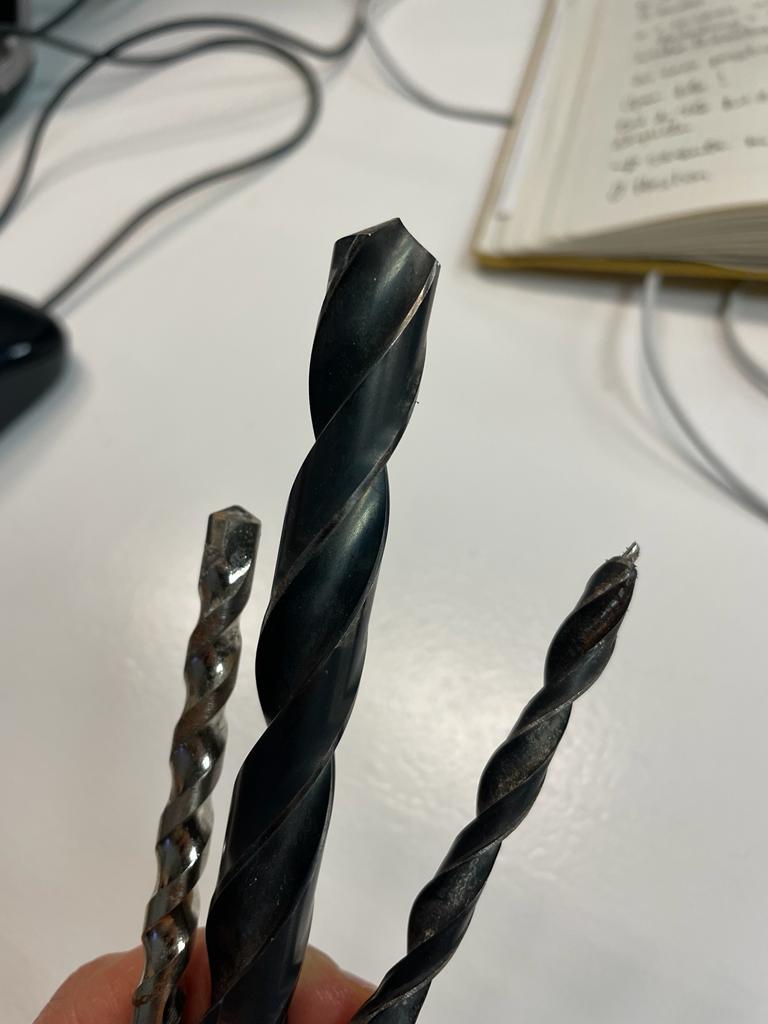
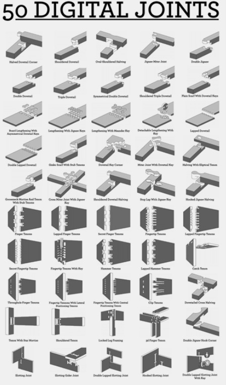
There are many different milling bits. Which one we choose depends on what we want to do. There are also many different ways to join wooden parts, and many different joints.
Safety rules
Safety is very important when it comes to CNC machining. We must always observe the following rules:
- Where is the emergency stop?
- Where is the fire extinguisher?
- The machine must always be able to work freely without anything leaning on it
- Never touch the machine while it's operating
- Always observe the cut
- Wear safety glasses
- Wear ear protection
- It is advisable to wear a mask as well
Design for Machining
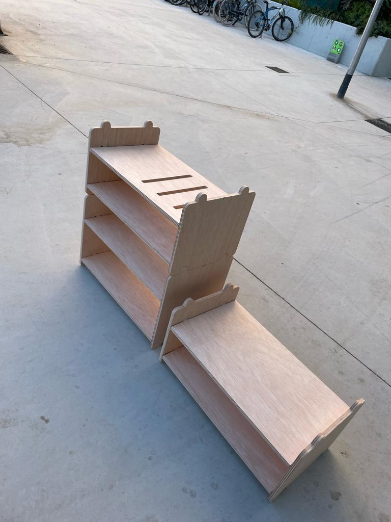
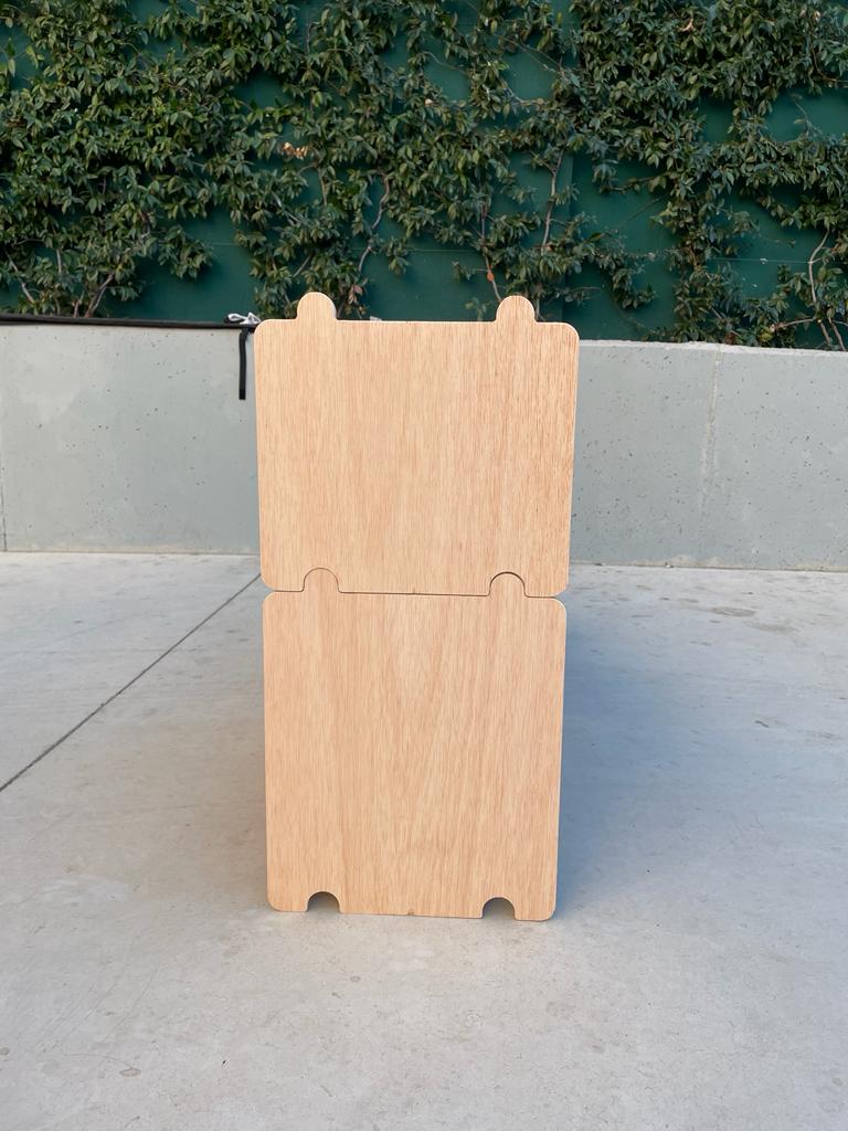
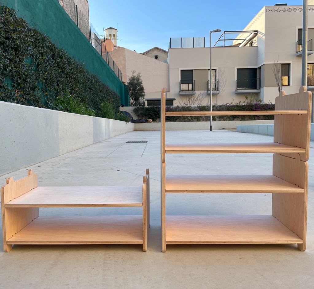
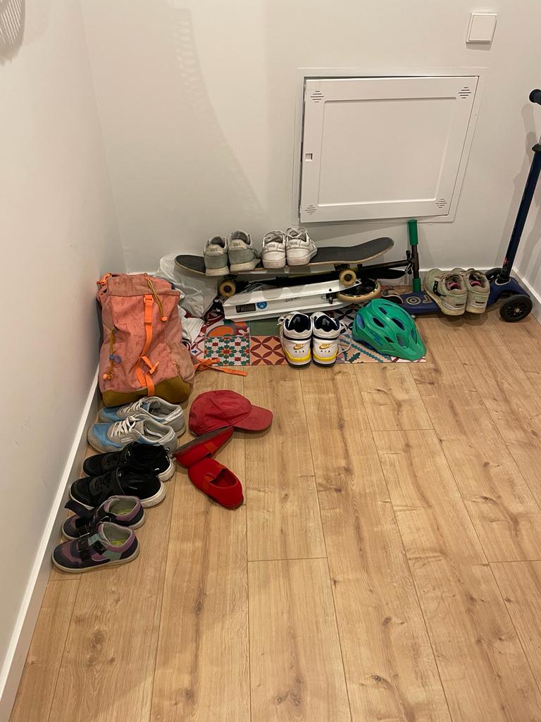
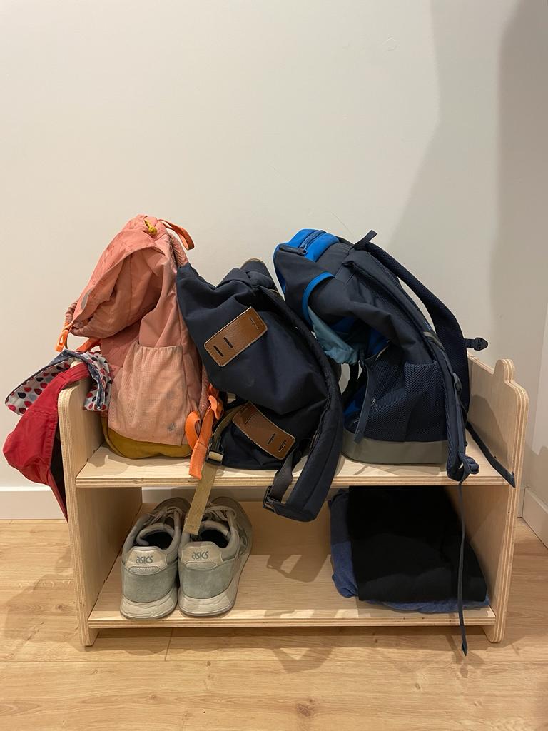
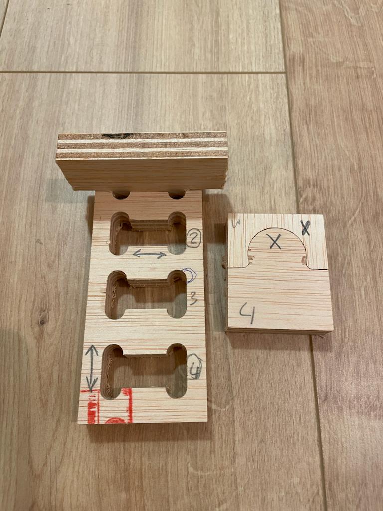
Since we have just moved into a new apartment and have very few furniture pieces, I decided to build a shelf for our hallway. I wanted it to be modular so that we could decide whether to place the individual elements side by side or on top of each other. Additionally, I wanted us to be able to store backpacks, helmets, and skateboards on the shelf. I then determined two shelves for each shelf unit. Additionally, I modeled circles to connect the individual boards. The top circles can also be used to attach bike helmets. Additionally, I planned holes in one board to have a place for skateboards.
I worked on my initial sketch with Fusion, as I had also worked with Fusion for laser cutting and therefore found the program to be the most familiar. Since I have only limited experience with 3D design, creating the sketch took longer than expected. I worked in sketch mode and used the parameter option to be able to easily change individual parameters later if necessary.
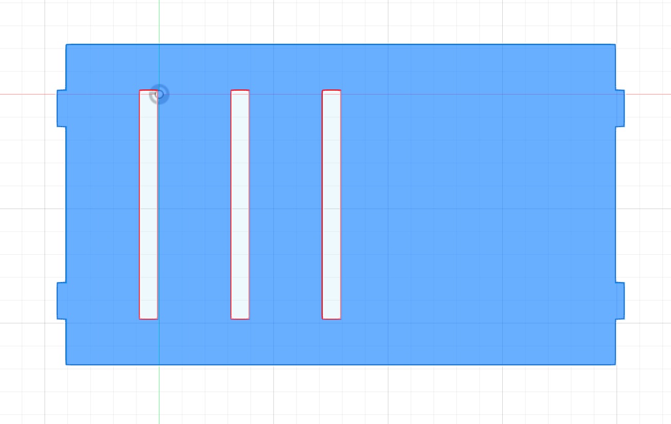
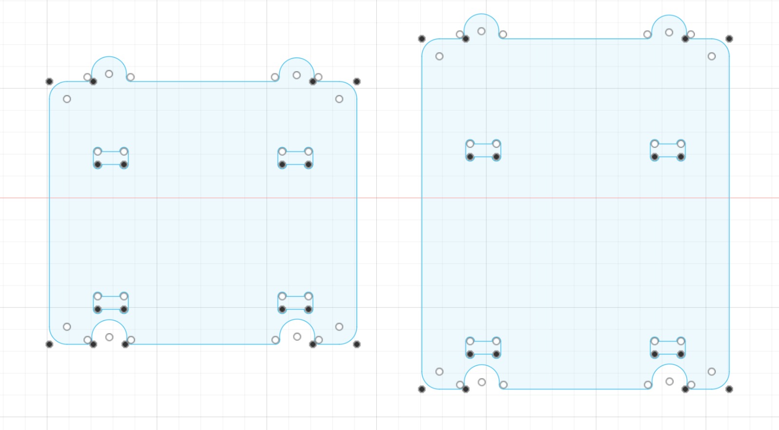
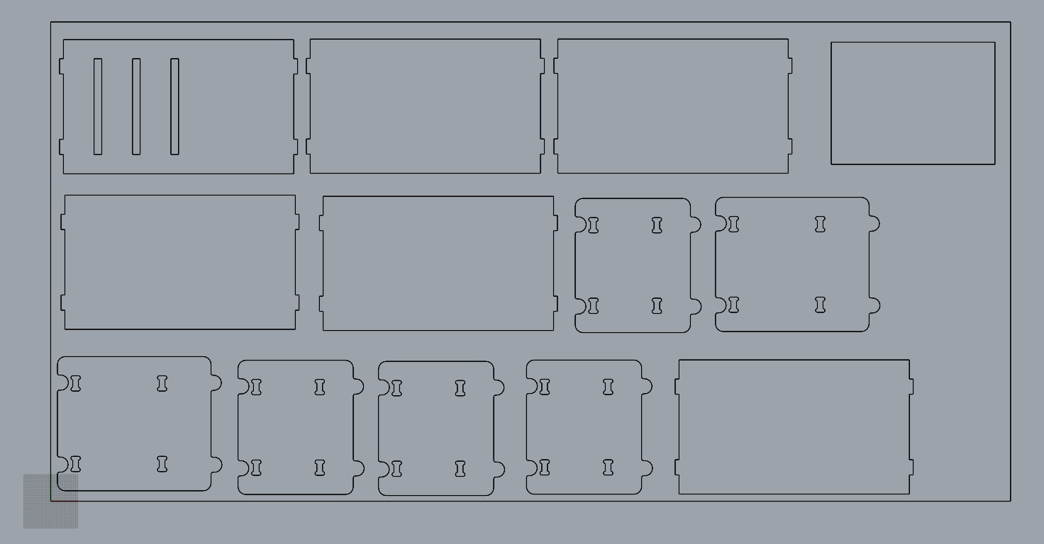
After the sketch was finished, I exported the individual parts as a DXF file and opened them in Rhino. I then created a cutting plan. To do this, I copied the parts as many times as necessary until I had the correct number. I placed them so that there was enough space between the parts so that they would not intersect during cutting. I saved the finished plan as a Rhino 6 file so that I could open it on the computer in the lab (which has the Rhino 6 version).
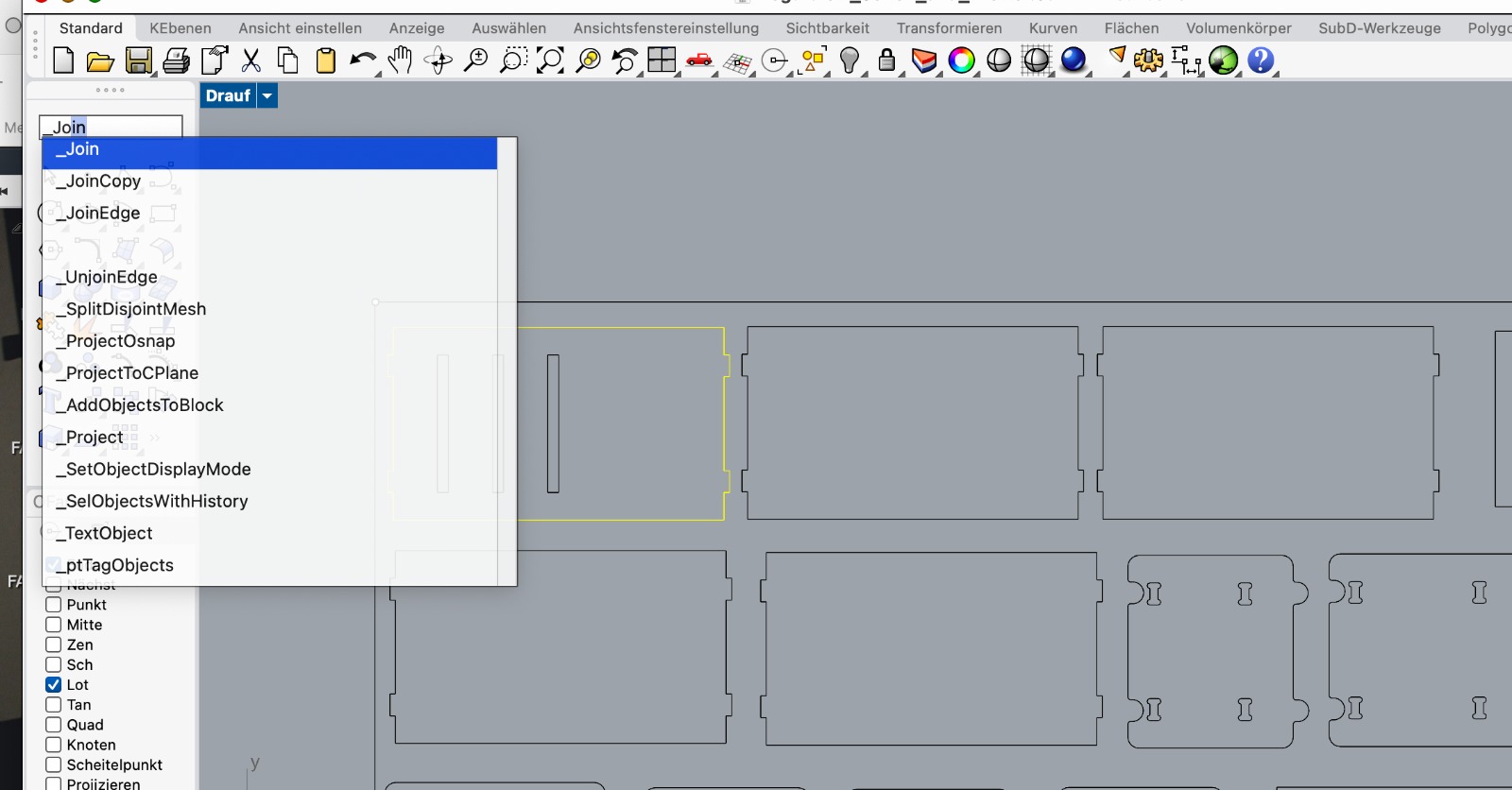
Then I prepared the file for cutting with Rhino CAM (I don't have the program myself). This took a long time. On the one hand, because I was not very familiar with the parameters yet, and on the other hand, because I confused the commands "group" and "join," or I was not clear that I had to join the individual elements of the sketch, it was not enough to group the elements. But when I finally understood that, it worked, and I was able to enter all the settings with Rhino CAM. Our model needs to be prepared for cutting after completion. The machine works with G-code. In theory, coordinates are forwarded to the machine.
Important terms for the process include:
- Roughening
- Finishing
- Profile
- Step Over
- Step Down
- Feed
- Plunge
- Lead in/Engage
- Pocketing
- Facing
- Stock
Furthermore, we need to consider that we have to secure our boards, for which we need an adequate number of screws. For a large board, four screws are usually not sufficient. It is also important to determine exactly where we will screw, so we mark the screw locations on our cutting plan from the beginning.
X is always the long side, Y is the short side at the front. Always consider whether outshape or inshape is needed, as this is super important for it to fit later. The material thickness must always be tested, as it often varies. Nesting is always important to save as much material as possible.
Rhino CAM Settings
Create/Select Tool:
- Select which tool you will use, in my case it was: Flat Mill
- 1 axis
- 6 mm
- Speed 20.000
- Plunge Approach Engage all 2500
- Cut Retract Departure all 4000
- Select Use Rapid
Now the tool with all the settings can be selected in the other steps.
Hole Profiling
Before performing the hole profiling, points need to be drawn on the cutting plan. For a large wooden board, it is advisable to use at least 9 screws, but depending on the type of cut, more or fewer may be necessary.
- With select curve/edge regions all points have to be selected
- Tool: Select Tool (which I prepared before)
- Sorting: No sort
- Feeds & Speeds: Speed: 20.000; Plunge/Approach/Engage all 2.500; Cut/Retract/Departure all 4.000; Select use rapid
- Cut parameters: Tolarance: 0.03; Select at top
- Enty/Exit: Lines and Arcs; Tangent; Radial Radius 6.35; Lines Arcs Radial Radius 6.35; Departure Motion Tangent
- Clearance plane: Part Max Z:6 - Stock Max Z: 25 - Absolute Z Value: 6
Axis Profiling
- First remove all of the selected parts an than select new with curve/edge regions all pockets have to be selected
- Tool: Select Tool (which I prepared before)
- Sorting: Minimum Distance Sort
- Feeds & Speeds: Speed 20.000; Plunge/Approach/Engage all 2.500; Cut/Retract/Departure all 4.000; Select use rapid
- Cut parameters: Tolerance: 0.03; Stock 0; Cut Direction: Climb; Use Mid-Point of longest side; Cut Start Side: Right; Use Outside/Inside for Closer Curves: Outside
- Cut Levels: Cut Levels; At top; Total Cut Depth: 15.3 (Depends on the thickness of the board); Rough Depth: 15.3; Rough Depth/Cut: 3; Cut Levels Ordering: Depth First
- Entry/Exit: Along Path; Approach Motion Length 6.35; Lines and Arcs None
- Clearance Plane; Part Max Z:6 - Stock Max Z: 10 - Absolute Z Value: 6
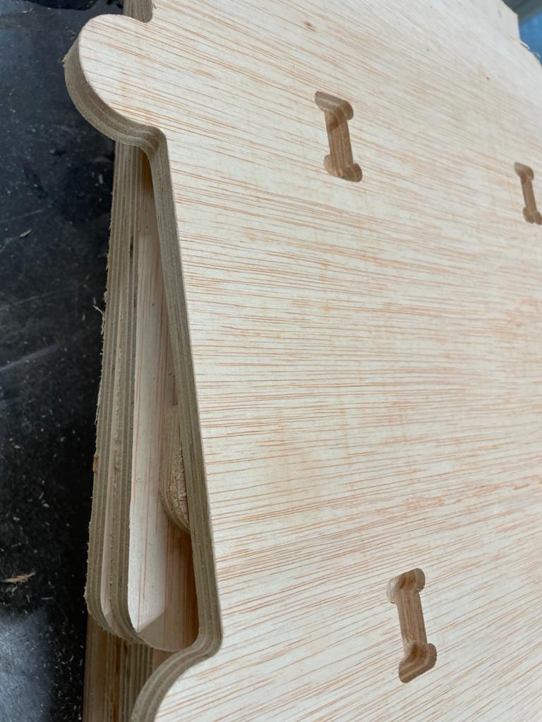
- Advanced Cut Parameters: Perform Arc Fitting; Bridges/Tabs, Rectangular, Bridge Heigth 3, Bridge Length 4, Number of Bridges 6 (it depends on the size of the pieces)
Once we have everything set up correctly, we select the "Post" option and save the file as an NC file. After that, we upload the file to the Fabcloud to later access it on the CNC machine. We should save two files. One file should contain the information for the screws, and the other file should contain all other information. The files should be organized so that the pocketing is done first, followed by the outlines.
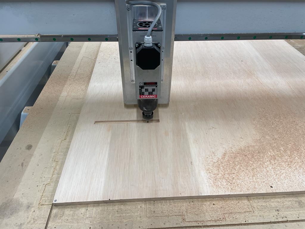
Going to the machine
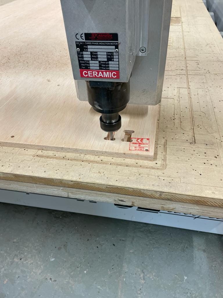
First, we need to load our material, in this case, our 15 mm plywood board, onto the machine. To do this, we initially move the spindle to the end of the machine. Then we choose a line where we can align our board so that it is perfectly straight.
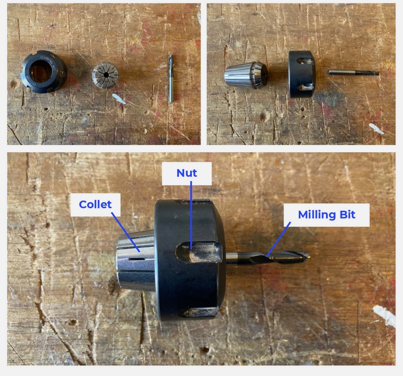
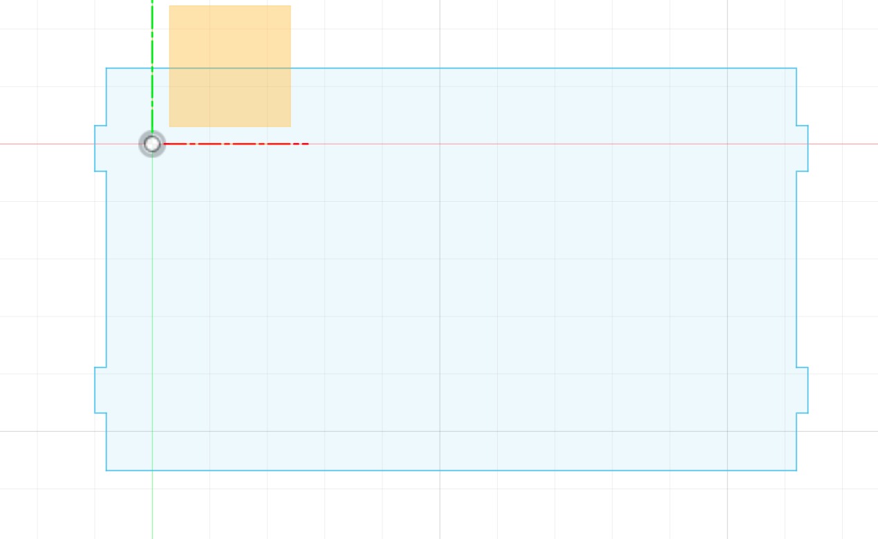
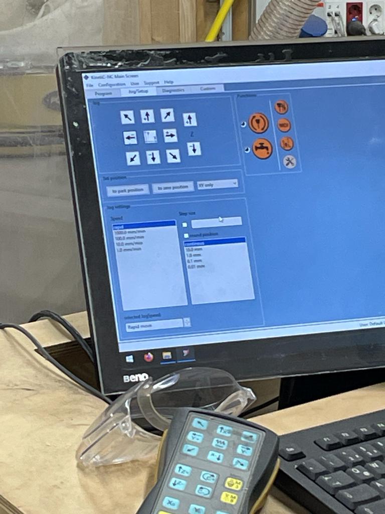
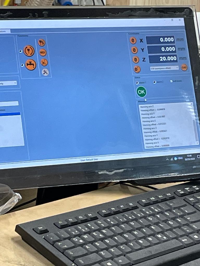
Next, we move the spindle forward to fix the tool. To do this, we open the nut, we clean nut and collet, and insert the milling bit. Then we reassemble collet, nut and milling bit securely. Then, we set the XY value to 0. To do this, we first move the arrows on the monitor. It is important that Z is not 0 so that the milling bit does not screw into the wood and get damaged. Once we have approached the XY value as closely as possible, we take the remote control and approach the machine. We navigate the enmill to the right front corner. When the endmill reaches the corner precisely, we set 0 on the screen. Now that we have xy = 0, we move the tool back to the middle and set z = 0. To do this, we slowly move the spindle toward the board with the remote controls and turn the nut. When the endmill touches the board straight but has not yet turned in, we stop and can now hold z = 0. We then move the spindle back up.
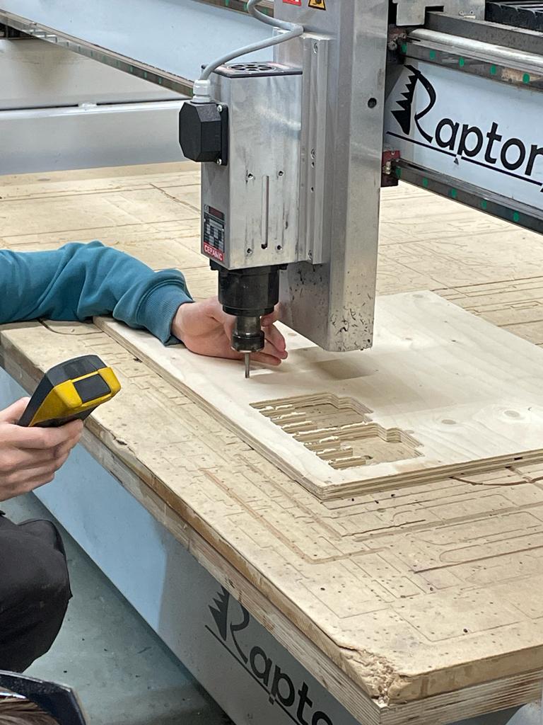
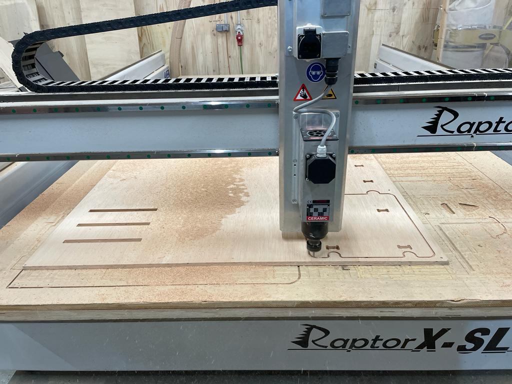
Next, we open our first file via the screen to determine the positions of the screws. After opening the file, we press start, and the machine starts marking the positions of the screws. When it's finished, we move the spindle all the way back and secure the board at the appropriate positions with screws and a cordless screwdriver. Then, as described above, we need to set the value Z = 0 again (as described above). Once we've done that, we open our second file through the cloud. Again, we click on Start, and the machine begins cutting. First, the pocketings are performed, followed by the outlines.
Once the cut is complete, the milling bit is moved back. First, the bridges are removed with a chisel and hammer, and the wooden parts are taken out. Then the screws are removed, and the board can be taken off the machine. Afterwards, the work area is vacuumed and cleaned.
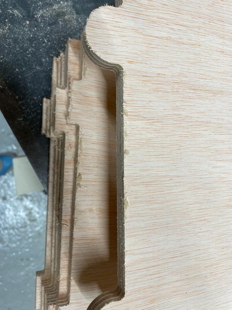
First Cut
I initially made a test cut to measure the pocketing. It turned out that I then incorporated the corresponding parameters into my cutting plan.
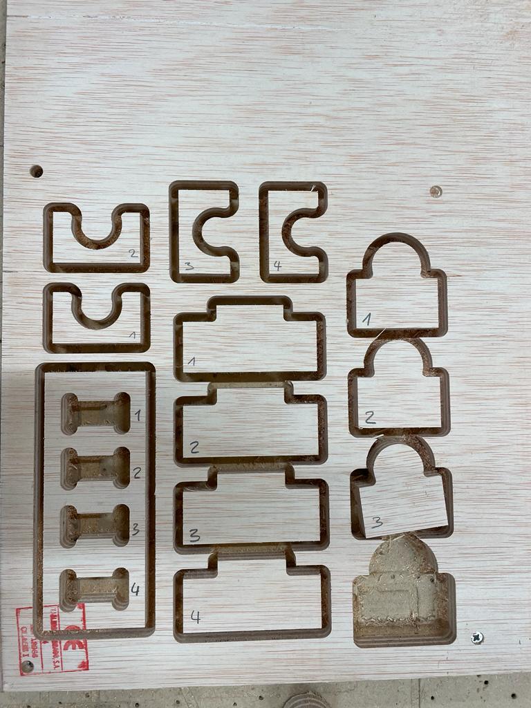
The following parameters I have selected and incorporated into my cutting plan
- Length Tennon - 0.1
- Height Tennon - 3
- Length Mortise - 0.3
- Height Mortise +/- 0
- Circle - 0.3
- Circle Outcut - 0.1
Second Cut
The second and final cut took approximately one hour.
Once the cut is complete, the spindle is moved back. First, the bridges are removed with a chisel and hammer, and the wooden parts are taken out. Then the screws are removed, and the board can be taken off the machine. Afterwards, the work area is vacuumed and cleaned.
After the cut, the wooden parts still need further processing. For this, all areas are sanded with sandpaper. In the end, the parts can be assembled.